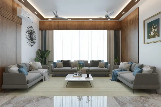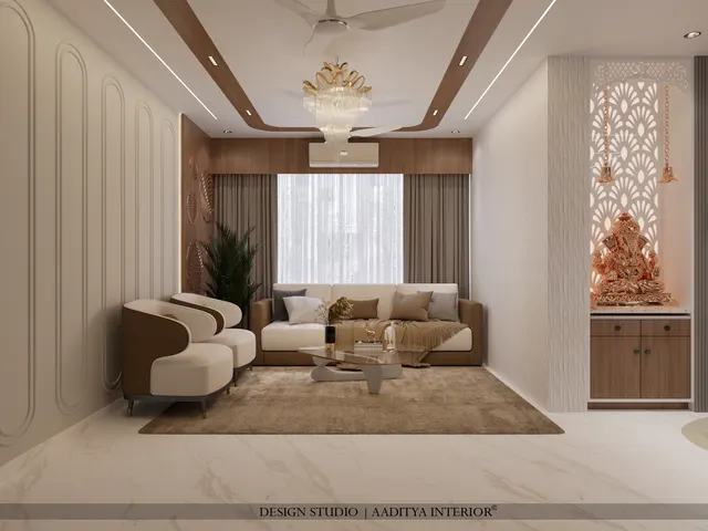



Ask a hundred households where their air-conditioner should go and most will point at the wall above the window or opposite the bed and say "there, near the top". Usually that is roughly right. But the details — exactly how high, how far from the ceiling and the side walls, which direction it blows, where the pipes leave the room, where the water goes and where the outdoor unit sits — decide whether the AC cools evenly and quietly for fifteen years or drips on the wall, blows cold air on someone's head and works twice as hard as it should.
In Indian homes these decisions are often made by the installation technician on the day the AC arrives, after the false ceiling, cove lights, curtain pelmets, wardrobe lofts and paint are finished. The technician then has to fit a 300 mm high unit into whatever wall is left, drill a pipe hole through a freshly painted wall and find a ledge for the outdoor unit that may have no air around it. Almost every common AC complaint traces back to that sequence.
This article sets out the heights, clearances and placement rules that should be decided at the design stage, for wall splits, cassettes and outdoor units. One important caution runs through it: there is no single national standard that fixes these numbers for every AC. Clearances are specified by each manufacturer in the installation manual for each model, and those figures always take precedence. The values here are the typical ranges found in Indian practice and in manufacturers' published manuals, given so that interiors can be planned with enough space. Electrical work should follow the National Building Code of India 2016, Part 8, and be carried out by a licensed electrician; refrigerant work should be done by trained technicians.
From window units to splits: why placement changed
For several decades the Indian home air-conditioner was the window unit: a single box set into a hole in the external wall or a window frame, usually at about window-sill or lintel height, with the hot side outside and the cold side inside. Its placement was fixed by the window. When split air-conditioners became affordable in the 2000s, the noisy compressor moved outside and the indoor unit moved to the top of the wall, where it could throw air across the whole room. That freed the window but created three new design questions that every home now faces: where the indoor unit goes on the wall, where the outdoor unit sits on the facade, and how the pipes and drain connect them.
Buildings took time to catch up. Many older apartment blocks have no planned ledges for outdoor units, so they hang on brackets beside windows or crowd into narrow ducts. Newer projects increasingly provide AC ledges with screens and drain points, and some high-end buildings provide refrigerant shafts for VRF systems. The direction is towards planning the air-conditioner as part of the building and the interior, not as an appliance added afterwards — which is the theme of everything below.
| Period | Typical AC in Indian homes | Placement decided by | Typical problem |
|---|---|---|---|
| Before the 1990s | Few ACs; window units in some homes | The window or a wall sleeve | Noise inside; blocked daylight |
| 1990s–2000s | Window units, early fixed-speed splits | Window, then the top of the wall | Outdoor units on any ledge |
| 2010s | Inverter splits; cassettes and ducted in larger homes | Wall above window or opposite bed | Clashes with false ceilings and coves |
| 2020s | Inverter splits with current refrigerants; VRF in villas | Increasingly at the design stage | Recirculation in closed AC ducts and screens |
| Next | Planned AC ledges, shafts and drains in every new building | The architect and interior designer together | Retrofitting older buildings |
Wall split indoor unit: the height and clearances
A wall-mounted indoor unit is typically about 280–340 mm tall, 750–1100 mm wide depending on capacity, and about 200–250 mm deep. It draws room air in through the top grille and blows cooled air out through a louvre at the bottom front. That is why the space above it matters: if the unit is pushed hard against the ceiling or a cove, it cannot draw air in freely and its cooling and efficiency drop. Manufacturers' manuals specify a minimum gap above the unit — commonly in the region of 150 mm, though some models ask for less and some for more — and minimum gaps at the sides, usually of the order of 100–150 mm. The front must be unobstructed for the air to throw.
In a typical Indian room with about 2750–2900 mm from floor to slab, these requirements place the underside of a wall split at about 2100–2400 mm above the floor, which is where most Indian installations sit. Two things decide the exact height. The first is what is above: a false ceiling cove that drops 150–250 mm at the edge of the room, or a beam, can take away the space the unit needs above it, so the unit must be lowered or the cove stopped short of it. The second is what is below: the unit should normally sit above the door head line of 2100 mm so it does not clash with a door, a window frame or a wardrobe loft. In a 2850 mm room that leaves about 750 mm above the door head for the AC and its clearance, a fan and any ceiling drop — which is why the AC must be drawn on the ceiling plan and wall elevations, not added afterwards.
| Item (wall split indoor unit) | Typical value | Basis | Notes |
|---|---|---|---|
| Unit height | ≈ 280–340 mm | Manufacturer data | Larger capacities are wider and sometimes taller |
| Unit width | ≈ 750–1100 mm | Manufacturer data | 1.5–2 ton units are usually 900 mm or more |
| Gap above the unit | As per manual; commonly around 150 mm | Installation manual | Needed for the return air at the top grille |
| Gap at the sides | As per manual; commonly 100–150 mm or more | Installation manual | Keep clear of curtains, side walls and lofts |
| Underside above floor | ≈ 2100–2400 mm in a 2750–2900 mm room | Common practice | Above the door head; not so high that the gap above is lost |
| AC power point | ≈ 2100–2300 mm, beside the unit | Electrical layout practice | 150–300 mm below the ceiling or bulkhead; dedicated circuit |
| Pipe hole | ≈ 65–75 mm, sloping down to the outside | Common practice | Sleeved; position fixed before painting and furniture |
| Distance to the person | Air should not blow directly on a bed head or sofa back | Comfort | Let it throw along the room's length |
Placing the AC in a room
Height is only half the decision. The other half is which wall and which direction. A wall split throws air in a jet that drops as it cools and spreads; it cools a room most evenly when it blows along the room's longer dimension, above head height, so the air mixes before it reaches people. It is least comfortable when it blows straight at a bed head, a sofa back or a desk chair from a short distance — the classic cause of stiff necks and complaints of the AC being too cold even at 26 °C.
In bedrooms, the best position is usually the wall at the foot of the bed or a side wall, throwing air along or across the room above the bed rather than at the pillow. Where the bed head wall is the only option, keep the unit well away from the head, use the louvre to direct air upward and rely on a ceiling fan at low speed to spread it. In living rooms, place the AC on a short wall so it blows down the length of the room, above the seating rather than at the back of the sofa; in an L-shaped living–dining space, a unit in the corner or two smaller units often work better than one large one. Many Vastu guides also suggest the west or north-west wall for the AC; where that coincides with good airflow, it is an easy choice, and where it does not, air distribution and comfort should decide.
| Room | Preferred position | Avoid | Notes |
|---|---|---|---|
| Master bedroom | Wall at foot of bed or side wall, throwing along the room | Directly above or facing the bed head at short range | Check the wardrobe loft does not block the side gap |
| Children's or guest room | Side wall across the foot of the bed | Above a study desk where the jet hits the head | Lower capacity units are quieter |
| Living room | Short wall, throwing down the room's length | Behind or above the sofa back; over the TV | Large or L-shaped rooms may need two units or a cassette |
| Dining area | Side wall, throwing across the table at height | Directly over the table, cooling food | Combine with the living-room unit if open plan |
| Study or home office | Side wall, not behind the chair or over the screen | Facing the user's head | Keep the drain away from bookshelves |
| Office cabin | Wall opposite the desk or a ceiling cassette | Directly over the chair | Cassette in larger cabins and meeting rooms |
| Shop or showroom | Cassettes or ducted grilles spread across the ceiling | Wall units over displays | Coordinate with display lighting |
Fitting the AC with ceilings, curtains and storage
Most clashes happen at the top of the wall, where the AC competes with the false ceiling, cove lighting, curtain tracks, pelmets, beams and wardrobe lofts. The rule is simple: draw the indoor unit on the wall elevation and the reflected ceiling plan at the design stage, with its required clearances, and design everything else around it. Specifically, stop a cove or a bulkhead short of the unit, or lower the unit so the full gap above it is kept; keep curtain tracks and blinds clear of its sides; never place it inside a niche or under a loft that boxes in its air intake; and keep it away from heat sources such as a ceiling-mounted light fitting directly below it or a west-facing window that heats the wall.
| Element at the top of the wall | Typical depth or height | Conflict with the AC | Design response |
|---|---|---|---|
| False ceiling cove drop | 150–250 mm at the room edge | Removes the gap above the unit | Stop the cove 300–450 mm short of the unit, or lower the unit |
| Beam | Often 450–600 mm deep in flats | Unit forced below the beam soffit | Place the unit on a wall between beams, or plan a cassette |
| Curtain track or pelmet | 100–150 mm from the wall | Blocks the side or front of the unit | Keep the unit beyond the curtain stack |
| Wardrobe loft | To 2400–2700 mm | Blocks a side gap; trapped air | Keep the unit clear by at least the manual's side gap |
| Door head | 2100 mm | Unit clashes with a door frame | Keep the unit's underside above the door head line |
| Ceiling fan | Blade sweep 900–1400 mm diameter | Fan blades in the AC jet cause wobble and noise | Keep the fan out of the direct throw where possible |
Pipes deserve the same attention. Refrigerant lines and the drain should leave the wall directly behind or right beside the indoor unit, through a sleeved hole of about 65–75 mm that slopes slightly down to the outside so water cannot run back in. Exposed pipe runs across an internal wall are best avoided; where the outdoor unit must be some distance away, a concealed pipe chase or a pipe route inside a bulkhead should be planned before plastering, insulated fully and with access at joints. Each model has a maximum pipe length and a maximum height difference between indoor and outdoor units, given in its manual; long runs may need additional refrigerant and reduce capacity.
The outdoor unit: air, access and safety
The outdoor unit rejects all the heat removed from the room plus the compressor's own heat, so it must be able to breathe. If its hot exhaust air cannot escape and is drawn back into its own intake — called recirculation — the unit runs hotter, cools less and uses more electricity, and in severe cases trips on high pressure on hot afternoons. This is the most common outdoor-unit problem in Indian buildings, where units are often squeezed into narrow shafts, enclosed behind dense louvres or stacked facing each other across a duct.
Manufacturers' manuals typically ask for an open space in front of the fan discharge of 500 mm or more, a smaller gap behind the intake coil (often in the range of 100–300 mm), and gaps at the sides, with at least one side or the top open. Figures differ between models and between single and multiple installations, so the manual governs. In practice more space is always better: a unit on an open ledge with nothing within a metre or two in front performs noticeably better than one squeezed against a screen. If the society or the architect requires the units to be screened, the screen should be a widely spaced louvre or perforated panel with a high open area, set well away from the fan, and the louvre blades should direct the hot air outward and upward rather than back into the unit.
| Outdoor unit item | Typical value | Why | Who confirms |
|---|---|---|---|
| Front (fan discharge) | ≥ 500 mm open; more is better | Hot air must escape, not recirculate | Manufacturer's manual |
| Rear (coil intake) | Often 100–300 mm from the wall | Air enters through the back coil | Manufacturer's manual |
| Sides | Often 100–300 mm; one side or the top open | Additional intake path | Manufacturer's manual |
| Screen or louvre | High open area, set away from the fan | Dense screens trap hot air | Architect and HVAC contractor |
| Support | RCC ledge, or a bracket anchored into RCC or solid masonry | A falling unit is a serious hazard | Installer; structural engineer for unusual cases |
| Vibration | Anti-vibration pads or mounts | Reduces noise in the building | Installer |
| Drain | Continuous fall to a gully or drain stack | Water on facades and neighbours' balconies | Plumber and installer |
| Service access | Reachable without unsafe climbing | Cleaning and repairs for 10–15 years | Architect and society |
| Noise | Away from bedroom windows, including neighbours' | Compressor and fan noise at night | Designer |
Brackets, ledges and safety at height
An outdoor unit weighs tens of kilograms and sits on a facade above people. It must be fixed on a properly designed RCC ledge or on a bracket of adequate section anchored into RCC or solid masonry with anchors suitable for the base material — not into AAC block, hollow block or plaster without fixings designed for that material. Brackets should be galvanised or properly painted against rust, especially in coastal cities, and checked during every service. Installation at height is skilled and dangerous work: it should be carried out only by trained installers using proper fall protection, never by a technician leaning out of a window or standing on an unguarded ledge. Where outdoor units are on high-rise facades, the building's design should provide safe access for servicing.
Cassette and ducted units: clearances in the ceiling
Cassette and ducted units live above the false ceiling, so their clearances are about ceiling depth, drains and access rather than wall space. This site's guide to AC types and the guide to ducted AC and false-ceiling coordination cover them in detail; the essentials for placement are summarised below.
A compact cassette typically needs a clear ceiling void of about 250–350 mm, depending on the model, plus room for its drain to rise from the built-in pump and then fall continuously to an outlet; the pump's maximum lift is given in the manual. It hangs from the slab on threaded rods and must not bear on the ceiling grid. Because it blows in two or four directions, manuals usually specify a minimum distance from the unit to walls and tall obstructions on its discharge sides, often of the order of a metre or more, and a minimum height of the ceiling above the floor. Ducted units need more: often 350–450 mm of void over the unit and its main duct, a return-air path from every room served, and an access panel large enough to remove the fan and clean the filters. In a typical flat with a 3.0 m floor-to-floor height, beams of 450–600 mm and a false ceiling at 2600–2700 mm, cassettes fit between beams more easily than ducted systems.
Drains, power and the installation sequence
Every AC produces condensate — water removed from the air — and in a humid city such as Surat or Mumbai a single unit can produce a surprising amount on a monsoon day. The drain should fall continuously, at about 1:100 or steeper, from the unit to a gully, a floor trap or a dedicated drain stack; it should never discharge onto a facade, a neighbour's balcony or a pavement. Sags in the drain pipe hold water and cause the indoor unit to drip. Where a drain must cross a beam or run upwards, a cassette's built-in pump or a separate condensate pump is used, within the lift stated by the manufacturer.
Electrically, each AC should have its own circuit from the distribution board, sized and protected according to the manufacturer's rating and the electrician's design. In common practice a 1–1.5 ton split is fed with 2.5 sq mm copper cable on a 16–20 A MCB and a 2 ton unit with 4 sq mm cable on a 20–25 A MCB, with proper earthing; larger units are often hard-wired through an isolator near the unit. The AC point is usually placed about 2100–2300 mm above the floor beside the indoor unit, so the cable is short and hidden. Work should follow NBC 2016 Part 8 and the relevant IS wiring codes and be done by a licensed electrician.
| Stage | AC decision to make | Why at this stage |
|---|---|---|
| Layout and furniture plan | Type of AC in each room; indoor unit wall and throw direction | Everything else follows from it |
| Electrical layout | Dedicated circuits, AC point heights and positions, outdoor isolators | Wiring is concealed before plastering |
| Civil work | Pipe holes, sleeves, concealed pipe chases, drain points, outdoor ledges or brackets | Cutting later damages finished walls |
| False ceiling design | Cove stops, cassette or ducted voids, hangers, access panels | Ceiling is closed after this |
| Carpentry | Lofts and wardrobes clear of the unit's side gaps | Avoids boxing in the unit |
| Painting | Touch-up only around pre-planned holes | Clean walls at handover |
| AC installation | Pressure test, vacuum, insulation, drain test | Quality of installation decides life and bills |
What installation costs
Indicative October 2026 figures, consistent with this site's AC and electrical guides: standard installation of a wall split typically costs about ₹1,500–3,000, extra insulated copper pipe beyond the length included in the standard installation about ₹600–1,200 per metre, an outdoor stand or bracket about ₹1,000–3,000, and a dedicated AC point on its own circuit about ₹3,500–7,000. Compact cassettes add about ₹5,000–15,000 for installation plus drain and ceiling cut-out. Equipment prices are separate: a 1.5 ton inverter wall split costs about ₹35,000–60,000. Planning the positions in advance costs nothing and saves most of the extra charges.
| Item | Indicative cost (Oct 2026) | Notes |
|---|---|---|
| Standard wall split installation | ₹1,500–3,000 | Includes a short pipe length; confirm what is included |
| Extra insulated copper pipe | ₹600–1,200 per metre | Long runs reduce capacity; check maximum length |
| Outdoor stand or bracket | ₹1,000–3,000 | Galvanised or painted; anchored to RCC or solid masonry |
| Dedicated AC point on its own circuit | ₹3,500–7,000 per point | Cable, MCB, isolator or socket |
| Compact cassette installation | ₹5,000–15,000 | Plus drain and ceiling cut-out |
| 1.5 ton inverter wall split (equipment) | ₹35,000–60,000 | 3–5 star; brand and features vary |
Where AC placement is heading
The next decade will bring more efficient equipment, lower-impact refrigerants and smarter controls, but placement will matter more, not less. Refrigerants such as R290 are flammable and need trained installers and the clearances and ventilation that their manufacturers specify. Smart controls and sensors can adjust louvres and fan speeds to where people are in a room, which works best when the unit is placed to throw along the room in the first place. New buildings in Indian cities increasingly include designed AC ledges with drains, screens with high open area and refrigerant shafts for VRF, and green building guidance and the Energy Conservation Building Code push designers to reduce cooling loads through shading and insulation. The constant is the sequence: decide the AC early, draw it on the elevations and ceiling plan, and give it the air it needs.
Rules for placing an AC
- Read the installation manual of the actual model before finalising positions; its clearances override any rule of thumb.
- Mount a wall split with its underside at about 2100–2400 mm in a 2750–2900 mm room, keeping the full gap above it that the manual requires.
- Blow air along the room above head height — never directly at a bed head, sofa back or desk chair at short range.
- Stop coves, bulkheads, curtains and lofts clear of the unit's top and side gaps.
- Plan the pipe hole (about 65–75 mm, sloping out), concealed pipe route and AC point (about 2100–2300 mm) before plastering.
- Give the outdoor unit open air — commonly 500 mm or more in front — and never close it in with a solid or dense screen.
- Fix outdoor units on RCC ledges or properly anchored brackets, with safe access for servicing and trained installers working at height.
- Run every condensate drain with a continuous fall to a gully or drain stack — never onto a facade.
- Feed each AC on its own circuit, sized to the manufacturer's rating by a licensed electrician.
Frequently asked questions
What is the right height to install a split AC?
In most Indian rooms with 2750–2900 mm from floor to slab, the underside of a wall split sits at about 2100–2400 mm above the floor. The deciding factor is the gap the manufacturer's manual requires above the unit for return air — commonly around 150 mm — so the unit should be as high as possible while keeping that gap below the ceiling, cove or beam.
How much gap should be left between the AC and the ceiling?
Follow the installation manual of the unit; many models ask for about 150 mm, some less and some more. If a false-ceiling cove or bulkhead runs above the unit, either stop the cove short of the AC or lower the unit so the full gap is kept.
Can an AC be installed directly above the bed?
It can be fixed there, but it is usually uncomfortable: the cold jet falls on the sleeper's head and shoulders. A position on the wall at the foot of the bed or on a side wall, throwing air along the room, gives more even and more comfortable cooling.
How much space does an AC outdoor unit need?
Manufacturers commonly ask for 500 mm or more of open space in front of the fan, about 100–300 mm behind the coil and some space at the sides, with at least one side or the top open. The manual for the specific model decides. Avoid closed AC shafts, dense screens and units facing each other.
Can the outdoor unit be placed inside a closed balcony or duct?
Only if it still has the open air the manual requires. A unit in a closed balcony, a narrow duct or behind a solid panel recirculates its own hot air, cools poorly and uses more electricity. Where screening is needed, use a widely spaced louvre or perforated panel set away from the fan.
Sources & standards
- Bureau of Indian Standards — National Building Code of India 2016, Part 8 (Building Services), Section 2 (Electrical and Allied Installations) and Section 3 (Air Conditioning, Heating and Mechanical Ventilation)
- Bureau of Indian Standards — IS 1391 (Part 1) and (Part 2): room air conditioners, unitary and split types
- Bureau of Indian Standards — IS 732: code of practice for electrical wiring installations
- Bureau of Energy Efficiency — Standards and Labelling programme for room air conditioners
- Bureau of Energy Efficiency — Energy Conservation Building Code (ECBC 2017) and Eco Niwas Samhita (residential)
- ISHRAE and ASHRAE handbooks — air distribution and installation practice; manufacturers' installation manuals for split, cassette and ducted units (clearances are model-specific)
- Price ranges: indicative October 2026 estimates — confirm locally before budgeting