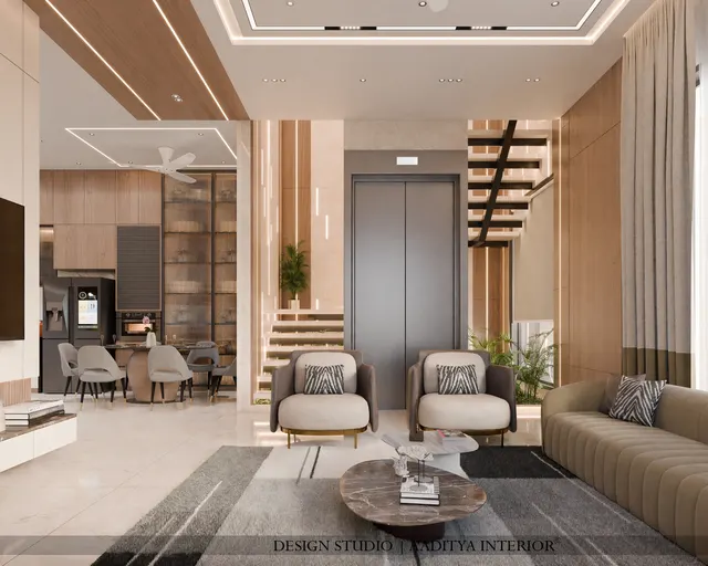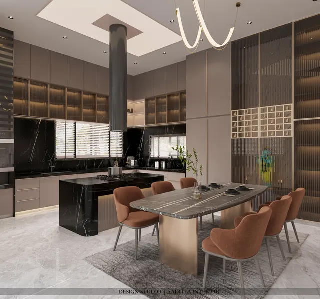



Many homeowners judge a design by its pictures. The designer presents a set of beautiful 3D renders — the living room at golden hour, the kitchen with glossy shutters, the bedroom with a glowing cove — and the family approves. Weeks later, on site, the carpenter asks how deep the TV unit should be, where the sockets go, what height the wardrobe loft starts, and which laminate code goes on the inner shelves. Nobody knows, because none of that is in a picture. The site improvises, and the finished room looks like a cousin of the render rather than the render itself.
The opposite problem is just as common. Some designers and contractors hand over a stack of CAD drawings — plans, elevations, sections — that are perfectly buildable but impossible for a family to read. The client signs drawings they do not understand and discovers what they approved only when the wardrobe is installed. Both failures come from the same misunderstanding: treating 2D drawings and 3D renders as alternatives, when they do different jobs. A render answers the question what will it look like. A drawing answers the question how exactly will it be built. A complete design needs both, tied to each other and to a written specification.
This article explains what each type of drawing and visual is for, lists the full set a homeowner should expect for a typical home interior, explains scales, sheets and revision control, shows what a good working drawing contains, gives indicative October 2026 costs consistent with this site's other guides, and ends with red flags to check before paying a design fee. It is general guidance; the exact drawing list for any project should be agreed in writing with the designer.
From blueprints to real-time renders
For most of the twentieth century, architectural and interior drawings were made by hand: pencil and ink on tracing paper, copied as blueprints or ammonia prints for the site. A drawing set was expensive to change, so it was carefully thought through before it was issued. Perspective sketches and watercolour renderings existed, but they were slow and costly, and most clients saw their home only as plans and elevations. Computer-aided drafting changed the drawing board first: AutoCAD, released in 1982, and similar programs made 2D drawings faster to produce and revise, and by the early 2000s most Indian design offices drafted on computers.
3D visualisation followed. Modelling and rendering software made photo-realistic images possible for ordinary residential projects, and over the last decade real-time rendering engines have made it possible to walk through a model live, on a screen or in a virtual reality headset. Building information modelling (BIM) now links 3D models to the 2D drawings and schedules generated from them, mainly on larger projects. AI image tools are the newest arrival, useful for mood and quick options but not for buildable drawings. Through all these changes, one thing has stayed constant: the site builds from dimensioned drawings.
| Period | How designs were shown | How sites were instructed | What changed |
|---|---|---|---|
| Before computers | Plans, elevations, occasional hand-drawn perspectives | Hand-drawn and printed drawings | Slow to change; clients saw few images |
| 1980s–2000s | CAD plans and elevations; early 3D | CAD drawings printed for site | Revisions became faster and cheaper |
| 2000s–2010s | Photo-realistic still renders for homes | CAD working drawings | Clients approved looks from images |
| 2010s–now | Real-time renders, 360° panoramas, VR, BIM on larger projects | CAD or BIM drawings, factory cutting lists | Images became cheap; drawings still decide quality |
| Emerging | AI-assisted concepts, AR on site | BIM-linked drawings and CNC files | Faster options; the need for dimensioned drawings remains |
What 2D drawings do — and what 3D renders do
A 2D drawing is a measured, flat representation — a plan from above, an elevation of a wall, a section cut through an object, or a detail at large scale — with dimensions, levels, material references and notes. It is a set of instructions. A 3D render is a computer-generated image of a 3D model with materials and light, seen from a chosen camera. It is a picture of an intention. The two are complementary, and the table below sets them side by side.
| Question | 2D drawings | 3D renders |
|---|---|---|
| What is it for? | Building: dimensions, positions, materials, quantities | Deciding: look, colour, mood, proportion |
| Who uses it most? | Carpenter, electrician, plumber, ceiling and tiling teams, factory | Family, designer, sometimes the society or developer |
| Does it carry dimensions? | Yes — every important size in mm | No — sizes can only be judged by eye |
| Can it hide problems? | Less easily: beams, pipes and clearances must be drawn | Yes: camera angle, wide lenses and lighting can flatter |
| What happens if it is missing? | The site guesses; quality varies by worker | The family cannot visualise; surprises at installation |
| Typical revision effort | Moderate; must stay consistent across sheets | Each changed view re-rendered |
| What to approve from it | Sizes, positions, clearances, materials, quantities | Colours, materials, overall feel — subject to samples |
Fig. 1 makes the difference concrete. The 3D view tells the family that the wardrobe will be warm wood with three shutters and slim handles. The elevation and section tell the carpenter that it is 2400 mm wide, 600 mm deep and 2100 mm high to the loft, that the loft is 450–600 mm, that the hanging rod is at 1700–1800 mm in the left bay, that shelves are at 300–350 mm spacing on the right, that the plinth is 100 mm and the carcass is 18 mm board. Only the second set can be priced, cut in a factory and checked at installation.
The complete drawing list for a home interior
A design package is easiest to judge when it is written down as a numbered drawing list, ideally attached to the design agreement. The exact list depends on scope — a two-room refresh needs far fewer sheets than a full 3BHK with civil changes — but for a full home interior the following drawings are normally expected. Many are produced once for the whole home; elevations and joinery drawings are produced room by room and unit by unit, which is why a fully detailed 3BHK set can run to several dozen sheets.
| Drawing | Typical scale | What it must show | Who uses it |
|---|---|---|---|
| Measured survey plan | 1:50 | As-built walls, windows, doors, beams, columns, levels, existing points | Designer; base for every other drawing |
| Civil changes plan (if any) | 1:50 | Walls to remove and build, new openings, door changes | Civil contractor, society approval |
| Furniture layout plan | 1:50 | Every furniture item with size, clearances, door swings | Family approval; base for services |
| Flooring plan | 1:50 | Material, tile size, laying direction, start point, level changes, thresholds | Tiling team |
| False ceiling plan (reflected ceiling plan) | 1:50 | Ceiling levels, coves, light positions, AC grilles, access panels | Ceiling and electrical teams |
| Electrical and lighting layout | 1:50 | Every switchboard, socket, light, fan, AC, data and TV point with heights; switching | Electrician |
| Plumbing layout | 1:50 | Inlets, outlets, geyser, floor traps, slopes, fixture positions | Plumber, waterproofing |
| Wall elevations, room by room | 1:20 or 1:25 | Panelling, paint and wallpaper areas, points on each wall, unit outlines | All trades, finishing |
| Joinery drawings (kitchen, wardrobes, TV, crockery, beds) | 1:20 with 1:5 details | Elevations, sections, internals, materials, hardware, edge and shutter details | Carpenter or factory |
| Details | 1:5, 1:2 or 1:1 | Junctions, profiles, cove sections, jaali fixing, skirting and threshold details | Specialist trades |
| Door and window schedule | — | Sizes, materials, hardware for each door | Carpenter, hardware supplier |
| Material and finish schedule | — | Codes, brands, grades and thicknesses for every surface | Everyone; protects specification |
Alongside the drawings, three documents complete the package: a specification sheet naming brands, grades and thicknesses; an itemised quotation or bill of quantities tied to the drawings; and, for 3D, a list of render views agreed in advance. This site's hiring checklist recommends that the drawing list and the number of revision rounds be written into the agreement, so that both sides know exactly what is being paid for.
Stage by stage: when each drawing arrives
Drawings and visuals arrive in stages, and the order matters. 3D renders made before the layout is frozen are wasted effort; joinery drawings made before the appliances are chosen will be redrawn. The timeline below follows the stages in this site's interior timelines guide for a mid-range 3BHK, where design before site work typically takes two to four weeks, or six to ten weeks when the home is fully detailed in 3D.
| Stage | Drawings and visuals delivered | What the family approves | Typical revision rounds |
|---|---|---|---|
| 1 · Brief and survey | Measured survey plan, site photos | That the survey matches the flat | — |
| 2 · Concept and layout | Two or three layout options, mood board, sometimes quick 3D massing | One furniture layout | 1–2 |
| 3 · Design development | 3D renders of key rooms, material board, preliminary estimate | Look, colours and materials (with physical samples) | 1–2 per view |
| 4 · Working drawings | Ceiling, electrical, plumbing, flooring, elevations, joinery, details, schedules | Sizes, positions and specification | 1–2 |
| 5 · Pre-production | Site re-measurement, final joinery drawings, cutting lists | Final unit drawings before factory production | 1 |
| 6 · Execution | Revised sheets (R1, R2…), site instructions | Changes, in writing, with cost and time | As needed |
| 7 · Handover | As-built drawings of services and concealed lines | Record for future repairs | — |
How to read a drawing sheet
A drawing sheet is a document, and every sheet should tell the reader what it is, at what scale it was drawn, and which version it is. Indian drawing practice follows IS 962 (Code of practice for architectural and building drawings) and the general engineering drawing conventions of SP 46, and sheets are usually ISO A-series sizes — A3 (420 × 297 mm) for most interior sheets, A2 or A1 for large plans. Three things on every sheet protect the client: the scale, so dimensions can be checked; the title block, which names the project, drawing title and number; and the revision box, which records what changed and when.
| Scale | Typical use | 1 mm on paper equals | Notes |
|---|---|---|---|
| 1:100 | Whole-flat key plans, building plans | 100 mm on site | Too small for joinery or points |
| 1:50 | Room plans: layout, ceiling, electrical, plumbing, flooring | 50 mm on site | The standard interior plan scale |
| 1:25 or 1:20 | Wall elevations, joinery elevations and sections | 25 or 20 mm on site | Shows shutters, shelves, points on walls |
| 1:10 or 1:5 | Details: cove sections, skirting, panelling joints | 10 or 5 mm on site | Where materials meet |
| 1:2 or 1:1 | Profiles, handles, edge details, jaali patterns | 2 or 1 mm on site | Often used for CNC files |
Two habits make drawings safe to use. Dimensions written on the drawing always override measurements scaled off the paper, because printing can shrink or stretch a sheet. And only the latest revision should be on site: when a sheet is revised, the old copy must be withdrawn, and the revision box should say exactly what changed. Many site errors come from a carpenter working from R0 while the designer has issued R2.
What a buildable joinery drawing looks like
The kitchen is the best test of a design package, because it combines joinery, appliances, plumbing, electrical points and stone in a small space. A buildable kitchen drawing does not just show the shutters; it shows heights, depths, appliance cut-outs, the sink and hob positions, the chimney height above the hob, every socket, the material code of each surface and the hardware in each unit. Fig. 4 shows the dimensions that should appear on a typical kitchen elevation.
The same standard applies to every built-in unit: a wardrobe needs internal elevations and a section; a TV unit needs the screen size, the socket and conduit positions and the cable route; a bed with storage needs the mattress size, the hydraulic or drawer system and the headboard height relative to the bedside switchboard. If a quotation lists a unit that has no drawing, the unit has no agreed design — only a name.
Renders, panoramas and walkthroughs: how many, and at what cost
The right number of render views depends on the home and the budget. For a typical 3BHK, about 12–25 still views usually covers the important angles: two or three for the living and dining area, one or two for the kitchen, two for each bedroom, and one each for the foyer, pooja and any feature wall. Renders should be made from the frozen layout, at a realistic eye height of about 1450–1600 mm for a standing view, with a lens that does not exaggerate the room — this site's guide on AI, VR and digital twins discusses camera honesty in more detail. Every material in a render should be confirmed with a physical sample before approval, because screen colours are not finish colours.
| Deliverable | Indicative cost (October 2026) | Typical quantity for a 3BHK | Worth it when |
|---|---|---|---|
| Design fee (full home, design and drawings) | Illustratively ₹100–250 per sq ft, or 8–12 % of project cost | Whole home | Always — compare what each fee includes |
| Photoreal still render | ≈ ₹2,000–10,000 per view | 12–25 views | Key rooms of any project |
| 360° panorama view | ≈ ₹3,000–12,000 per view | 2–6 views | Living rooms, sample flats |
| Animated walkthrough | ≈ ₹15,000–60,000 per minute | 1–2 minutes | Large homes, sales, hospitality |
| VR walkthrough of a home | ≈ ₹25,000–1,00,000 per project | Whole home | Large or complex homes |
| Extra revision rounds beyond agreement | Often charged per view or per sheet | As needed | Agree the rate in advance |
| Working drawings | Usually inside the design fee | Several dozen sheets | Never optional for a full interior |
Files, revisions and ownership
Most clients and site teams work from PDF drawings, which print reliably and cannot be accidentally edited. Editable CAD files (DWG) and 3D model files are a different matter: many designers treat them as their working files and do not hand them over by default, and copyright in drawings and designs generally stays with their author unless the agreement says otherwise. This is a contractual matter rather than a technical one, and it should be settled in writing before the work starts — including what happens to the drawings if the engagement ends early. This article is general information, not legal advice; for specific terms, consult a qualified professional.
| File | What it is for | Usually provided? | Agree in writing |
|---|---|---|---|
| PDF drawing set | Site use, printing, approvals | Yes | Number of sets, sheet sizes, revision issue |
| Render images (JPG or PNG) | Approval, sharing with family | Yes | Resolution, number of views |
| CAD files (DWG) | Editing, coordination with other consultants | Sometimes | Whether provided, and at which stage |
| 3D model files | Future changes, VR | Rarely by default | Whether provided and for what use |
| As-built services drawings | Future repairs and drilling | Should be | Include in the deliverables list |
Where design deliverables are heading
The line between 2D and 3D is blurring. On larger projects, BIM models already generate plans, elevations and schedules from one coordinated model, so a change made in 3D updates every drawing. Factories making kitchens and wardrobes increasingly work from model-based cutting lists and CNC files rather than hand-measured sketches. Augmented reality lets a family see a sofa or a wardrobe in their actual room through a phone. And AI tools are speeding up concept images and mood boards. None of this removes the need for a dimensioned, checked, revision-controlled drawing set. It changes how that set is produced, and it raises the bar for consistency: when the render, the drawing and the cutting list come from the same model, there is no excuse for them to disagree.
Rules for checking what you receive
- Ask for a written, numbered drawing list and the number of revision rounds before paying a design fee.
- Approve the furniture layout before any render is made, and renders only with physical material samples in hand.
- Make sure every built-in unit in the quotation has its own elevation and section drawing with dimensions in mm.
- Check that every sheet carries a scale, drawing number, date and revision; keep only the latest revision on site.
- Insist on ceiling, electrical and plumbing drawings before walls are chased or ceilings framed.
- Read dimensions from the drawing, never by scaling a printed sheet.
- Agree in writing which files you will receive (PDF, DWG, renders, as-built) and what happens to them if the engagement ends.
- Ask for as-built drawings of concealed services at handover.
Frequently asked questions
What is the difference between 2D and 3D in interior design?
2D drawings are measured plans, elevations, sections and details with dimensions, used to build. 3D renders are images of a 3D model with materials and light, used to decide how the space should look. A good design package ties the two together so the built room matches the image.
Which drawings should an interior designer give me?
For a full home: a measured survey plan, furniture layout, flooring plan, false ceiling plan, electrical and lighting layout, plumbing layout, wall elevations, joinery drawings and details for every built-in unit, a door schedule, a material and finish schedule, and as-built services drawings at the end. Smaller scopes need fewer sheets; agree the list in writing.
How much does a 3D render cost in India?
Indicatively, in October 2026, a photoreal still render costs about ₹2,000–10,000 per view, a 360° panorama about ₹3,000–12,000 per view, and an animated walkthrough about ₹15,000–60,000 per minute. Many studios include a set number of views in the design fee.
Is a 3D render enough to start work on site?
No. A render has no dimensions, internal layouts, material codes or service positions. Work on site should start only from dimensioned, approved 2D drawings, with the render used as a reference for appearance.
Can I get the CAD files from my designer?
Sometimes. Many designers provide PDFs as standard and treat editable CAD and model files as their own working files. If you need DWG files — for example for a future renovation or another consultant — agree it in the contract before work begins.
Sources & standards
- IS 962 — Code of practice for architectural and building drawings (Bureau of Indian Standards)
- SP 46 — Engineering drawing practice for schools and colleges (Bureau of Indian Standards)
- ISO 216 — Writing paper and certain classes of printed matter: trimmed sizes, A and B series
- Bureau of Indian Standards — National Building Code of India 2016, Part 2 (Administration: building permit drawings)
- Council of Architecture, India — conditions of engagement and scale of professional charges (guidance documents)
- Neufert, Architects' Data — drawing conventions, kitchen and storage dimensions
- Price ranges: indicative October 2026 estimates — confirm locally before budgeting