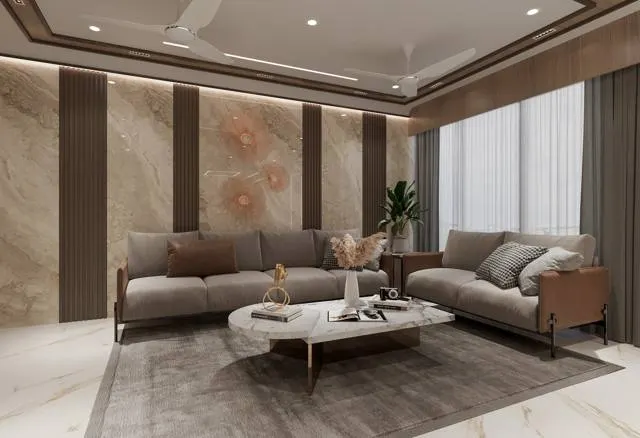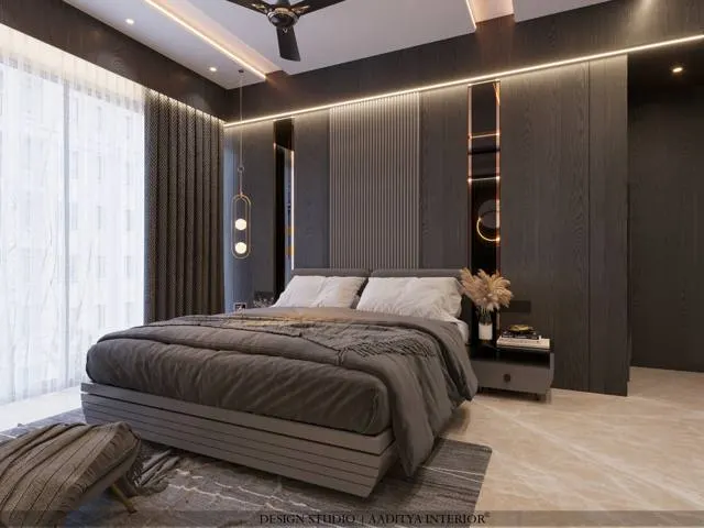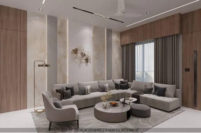



A ducted air-conditioner is the quietest-looking way to cool a home: no box on the wall, no pipes on the facade of the room, just slim grilles in the ceiling. In premium flats, penthouses and bungalows across Surat, Ahmedabad, Mumbai and Pune it has become the default request for living–dining spaces. But a ducted system is not an appliance that is hung and switched on. It is a small building service that lives inside the false ceiling, and it only works if the ceiling, the beams, the lights, the drains and the access are designed around it from the first drawing.
Most complaints about ducted AC in Indian homes are coordination failures, not equipment failures. The ceiling was dropped to 2400 mm in the whole living room because nobody checked the beam depth. The duct was squeezed flat under a beam and now whistles. The return air has no path out of the bedroom, so the room never cools. The drain was laid without a fall and drips onto a new sofa in the first monsoon. The unit was boxed in with no access panel, and the first filter cleaning means cutting the gypsum. Every one of these is avoidable on paper, at almost no cost, and very expensive to correct once the ceiling is painted.
This article walks through the coordination the way a site actually runs: how much void a ducted system needs, how to deal with beams, how to lay out supply and return grilles with the lights, how to detail the drain and the access panel, the order of work on site, and what the whole package costs in October 2026. It is written for homeowners who want to understand what their HVAC contractor and interior designer should be agreeing on, and for young designers who will have to draw it.
How a ducted system works, and what goes into the ceiling
A ducted or ductable AC is a split system: an outdoor condensing unit sits on a ledge, terrace or service yard, and an indoor fan-coil unit is hidden above the false ceiling, usually over a passage, a utility, a toilet lobby or a wardrobe loft. The indoor unit pulls room air in through a return grille, passes it over the cooling coil and pushes it into a supply plenum, from which insulated ducts carry it to grilles in the rooms. In a VRF installation the outdoor unit is shared and each room may have its own small ducted indoor unit; the coordination principles are the same, only multiplied.
Every one of these parts takes space, and every one has a service need. The unit needs hangers into the slab, room below for a drain trap and a filter that someone will slide out every few weeks in the dusty season. The ducts need height, and their insulation adds more. The refrigerant pipes and the drain need a continuous route to the outdoor unit and to a floor trap or rainwater pipe. The grilles need to land where the gypsum framing allows a cut-out and where the light layout does not already sit. The table below lists the parts and the space each one claims.
| Part | Where it sits | Space it needs (indicative) | Coordination note |
|---|---|---|---|
| Indoor ducted unit (1.5–5.5 TR) | Above passage, utility, toilet lobby or loft | Body about 250–300 mm high for slim units; 300–400 mm for high-static units | Must be reachable from below through an access panel |
| Supply plenum | Directly on the unit outlet | Same height as the unit outlet, 300–600 mm long | Distributes air to the branch ducts; keep it straight |
| Main supply duct | Along a passage or the window wall | 150–300 mm high plus 13–25 mm insulation | Sized by airflow; the deepest item after the unit |
| Branch ducts and collars | From main duct to each grille | 100–200 mm high, or flexible duct of 150–250 mm diameter | Keep flexible runs short and without kinks |
| Supply grilles or linear diffusers | In the ceiling board or a cove | Neck 100–200 mm wide; length to suit | Needs framing around the cut-out |
| Return grille and return path | Ceiling near the unit, or a wall grille | Free area close to the unit inlet size | Every served room needs a way for air to get back |
| Refrigerant piping and cable | From unit to outdoor unit | Two insulated copper pipes, about 50–80 mm bundle | Route fixed before ceiling framing |
| Condensate drain | From the unit drain pan to a floor trap or pipe | 25–32 mm pipe with insulation, falling all the way | Fall about 1:100; trap at the unit |
A short history: from cinema halls to living rooms
Ducted air-conditioning arrived in India the way it arrived in most hot countries: first in cinema halls, hotels, banks and offices, served by central plants with large ducts in deep ceiling voids. For decades it remained a commercial amenity. Homes cooled themselves with courtyards, high ceilings, jaalis and fans, and later with window units. When split ACs became common in the 2000s, the larger homes began to use ductable splits — a single indoor unit hidden over a passage, feeding the living and dining room through ducts. The 2010s brought inverter compressors and VRF systems, which allowed several small ducted units on one outdoor unit and made per-room control realistic in villas and penthouses.
What changed most in the same period was the false ceiling. Gypsum board on galvanised steel framing replaced POP on chicken mesh as the standard for Indian homes, and it made ceiling cut-outs, linear diffusers, cove lights and access panels clean and repeatable. Ducted AC and gypsum ceilings grew up together: one hides the services, the other carries the grilles. That is why the two trades must now be drawn together and built in a fixed order.
Ceiling void depth: how much space a ducted AC really needs
The single most important number is the depth of the void between the slab soffit and the finished ceiling. Over the indoor unit and the first stretch of the main duct, a residential ducted system typically needs about 350–450 mm of clear void. Away from the unit, where only branch ducts or flexible ducts run, the void can often reduce to about 250–300 mm. And in rooms that receive only a grille at the edge, the ceiling can stay higher still, with a local bulkhead carrying the duct. Good coordination uses these differences instead of dropping the whole flat to the lowest common level.
The void is a stack of small dimensions, and each one is real: a gap of about 25–50 mm between slab and unit for the hanger nuts and anti-vibration pads; the unit body itself; a clearance below the unit for the drain trap and for sliding out the filter; the gypsum framing; and the board. Ducts add their own insulation, commonly 13–25 mm of closed-cell nitrile or similar on each face, which is easily forgotten when a 200 mm duct is drawn as 200 mm instead of about 240–250 mm overall.
The table below turns the stack-up into planning numbers. Combine it with the room's slab-to-slab height: most Indian flats have a floor-to-floor height of about 3000–3200 mm, which leaves a structural clear height of roughly 2850–3050 mm below a 150 mm slab. Taking 450 mm off that gives a finished ceiling of about 2400–2600 mm at the unit — acceptable over a passage, but heavy over a living room. That arithmetic is the reason the unit should almost never sit over the main room.
| Zone | Typical void needed | Resulting ceiling in a 2900 mm clear room | How designers use it |
|---|---|---|---|
| Over the indoor unit and plenum | 350–450 mm | 2450–2550 mm | Place over passage, toilet lobby, utility or loft |
| Main supply duct run | 300–350 mm | 2550–2600 mm | Run along the passage or as a bulkhead on the window wall |
| Branch or flexible ducts only | 250–300 mm | 2600–2650 mm | Room centre can stay at this level |
| Grille-only edge of a room | Duct in a perimeter bulkhead, 300–600 mm wide | Centre of room 2700 mm or more | Cove bulkhead hides the duct and carries the lights |
| No duct above (bedrooms with wall splits) | 100–150 mm for lights only | 2750–2800 mm | Keep ceilings high where no air is distributed |
| Under a 300 mm deep beam | Duct must pass below or beside the beam | Local drop to about 2450–2500 mm | Treat as a feature band, not an accident |
Beams: the real obstacle, and how to get past them
In a typical RCC flat, beams of 230 mm width and 450–600 mm overall depth cross the living room, and the duct must get from one side to the other. The beam is the reason most ducted ceilings end up lower than they need to be. Before anything is drawn, a designer should survey every beam in the flat — position, width and depth below the slab — and mark them on the reflected ceiling plan. The survey takes an hour with a laser distance meter, and it decides the whole ceiling.
There are three good answers and one bad one. The first is to route the duct parallel to the beams, so it never has to cross them; this often means taking the main duct along the passage and turning into each room between beams. The second is to flatten the duct where it passes under a beam: a 300 × 200 mm duct can become a 500 × 120 mm duct for that stretch, carrying roughly the same air, as long as the aspect ratio (width to height) stays at about 4:1 or less and the transitions are gradual. The third is to accept a local bulkhead under the beam and make it part of the design — a cove band, a lighting trough or a change of ceiling level between living and dining. The bad answer is to cut a hole through an existing beam. Openings in beams can only be made where a structural engineer has designed them, ideally as sleeves cast in before the concrete is poured; core-cutting an existing beam can cut reinforcement and weaken the frame, and it should never be done on a contractor's say-so.
Option B deserves a caution. A flattened duct carries the same air at a similar velocity only if its cross-sectional area is kept. A 300 × 200 mm duct has an area of 0.06 m²; a 500 × 120 mm duct has the same 0.06 m², but a 500 × 80 mm duct has only 0.04 m², which forces the air to move about fifty per cent faster through that section — a recipe for whistle and lost airflow. Ask the HVAC contractor to show the area check on the shop drawing whenever a duct changes shape.
Sizing the airflow, ducts and grilles in plain numbers
Residential ducted systems are commonly designed around an airflow of roughly 350–400 cubic feet per minute (CFM) per ton of refrigeration (TR), and quiet homes keep the air speed in the ducts low — typically about 4–5 m/s in mains and lower in branches and at the grille faces. The duct sizes in the table below follow from those two assumptions. They are indicative, meant to help a homeowner or designer judge whether the space allowed in the ceiling is realistic; the HVAC designer will size the actual ducts by a friction or equal-friction method and check the external static pressure the unit can deliver.
| Unit size | Approximate airflow | Indicative main duct (low velocity) | Typical number of supply outlets | Return grille free area (indicative) |
|---|---|---|---|---|
| 1 TR | 350–400 CFM | 250 × 175 mm | 2 | About 0.07–0.09 m² |
| 1.5 TR | 525–600 CFM | 300 × 200 mm | 2–3 | About 0.10–0.13 m² |
| 2 TR | 700–800 CFM | 400 × 200 mm | 3–4 | About 0.13–0.17 m² |
| 3 TR | 1,050–1,200 CFM | 500 × 250 mm | 4–6 | About 0.20–0.25 m² |
| 4 TR | 1,400–1,600 CFM | 650 × 250 mm | 6–8 | About 0.26–0.33 m² |
| 5.5 TR | 1,900–2,200 CFM | 750 × 300 mm | 8–10 | About 0.36–0.45 m² |
Supply outlets come in three common types. Linear slot diffusers — one to four narrow slots in an aluminium frame — sit along a window wall or inside a cove and almost disappear. Square or rectangular diffusers sit in the ceiling field and throw air in several directions. Concealed grilles in the vertical face of a bulkhead push air horizontally across the room and suit rooms with a cove band. The number of outlets in the table is a guide; each outlet's actual capacity and throw come from the manufacturer's selection data, and an outlet that is asked to deliver too much air will be noisy and create a cold draught on the sofa below it.
The return-air path nobody draws
Air pushed into a room must have a way back to the unit. In an open living–dining space this is easy: a return grille in the passage ceiling near the unit, and the air simply drifts back. The trouble begins when one ducted unit serves closed rooms. A bedroom with a supply grille and a closed door becomes pressurised; less air enters, the room never cools, and the door whistles. Each closed room on a shared unit needs a return path: a ducted return, a transfer grille above the door, or a door undercut of about 20–25 mm, depending on the airflow. This is also why most designers prefer separate units — a small ducted VRF indoor unit or a wall split — in bedrooms, and keep a single ducted unit for the open living–dining zone.
Grilles, lights and detectors: drawing one reflected ceiling plan
The reflected ceiling plan (RCP) is the drawing where AC and ceiling coordination either happens or does not. It should show, on one sheet: the beams, the ceiling levels and bulkheads, every supply and return grille with its size, every light, the smoke detectors if any, speaker or sensor positions, curtain pockets, and the access panels. When the AC contractor works from one drawing and the lighting designer from another, grilles land on top of downlights, diffusers blow straight at a smoke detector, and the curtain pocket collides with the linear slot. The plan below shows a coordinated living–dining room.
A few relationships repeat on almost every project. Put supply outlets where the heat enters — along the window wall, especially on west and south sides — and let the return be at the opposite side or near the unit, so the air crosses the occupied space before it returns. Never put a supply and a return grille close together, or the air short-circuits straight back to the unit without cooling the room. Keep supply outlets out of the line of a sofa back or a dining chair, where a cold jet lands on someone's neck. Line up grilles and lights on one geometric logic — a common centre line, a common offset from the wall — so the ceiling looks designed rather than punctured.
| Relationship | Typical guidance | Why it matters |
|---|---|---|
| Supply outlet to window glass | About 200–400 mm off the wall | Washes the hot surface and stops condensation streaks on the glass |
| Supply outlet to return grille | As far apart as the room allows, ideally on opposite sides | Prevents short-circuiting and uneven cooling |
| Supply outlet to downlight | About 600–900 mm or more | Avoids dust streaks round lights and keeps the ceiling orderly |
| Supply outlet to smoke detector | Commonly at least about 1 m — confirm with IS 2189 and the fire designer | Air jets can delay or disturb detection |
| Supply outlet to curtain pocket | Slot inside or just in front of the pocket, not behind it | Air must reach the room, not the back of the curtain |
| Grille to seating position | Not directly above a sofa back, bed head or dining chair | Avoids cold draughts on the neck and shoulders |
| Access panel to unit | Directly below the filter and drain side | Allows filter cleaning without touching the gypsum |
Drain, insulation and access: the details that cause leaks
Water damage from ducted AC almost always comes from three sources: the condensate drain, uninsulated cold surfaces, and service visits that damage the ceiling. A ducted unit can produce several litres of condensate an hour in a humid Surat or Mumbai monsoon, and that water must flow by gravity, without a single low point, to a floor trap, a rainwater pipe or a dedicated drain. A fall of about 1:100 is the usual minimum; a trap at the unit outlet stops air being sucked back through the drain; and the drain line itself is insulated so that it does not sweat onto the gypsum. Where a gravity fall is impossible, a condensate pump is used, but a pump is one more thing that can fail, and its overflow must be wired to stop the unit.
Cold surfaces sweat. Every supply duct, the plenum, the refrigerant pipes and the drain must be continuously insulated, with joints taped and no gaps at hangers or collars. A bare patch the size of a palm is enough to create a brown ring on the ceiling within a few weeks of the first humid season. Return ducts and plenums inside the air-conditioned envelope are sometimes left bare, but in humid coastal cities designers usually insulate them too.
Access is the last of the three. A ducted unit needs regular filter cleaning — monthly in dusty seasons is common — plus coil cleaning and occasional repairs. That requires an access panel of at least 600 × 600 mm, directly below the filter and drain side of the unit, framed on all four sides so the gypsum does not crack when it is opened. Push-latch or hinged gypsum access doors with a narrow aluminium frame look tidy and can be painted with the ceiling. Where the unit sits over a toilet lobby, the panel can sometimes be in the toilet ceiling; where it sits over a wardrobe loft, the loft back can be made removable. What must never happen is a unit sealed in, with the access left to be cut later.
The site sequence: who does what, and when
Ducted AC and false ceilings are installed by different teams, and the most common site problem is the ceiling team closing a void before the AC team has finished testing it. The sequence below avoids that. The two hold points — pressure and drain testing before insulation is closed, and a joint inspection of the void before boarding — are where the designer or site supervisor should be present in person.
| Stage | Team | What to check | Common mistake |
|---|---|---|---|
| Beam survey and RCP | Designer + HVAC contractor | Every beam's position and depth; unit location; duct route | Designing the ceiling before measuring the beams |
| Core holes in walls | Civil or core-cutting contractor | Pipe and drain holes sloping outwards; no holes through beams or columns | Drilling through a beam because it was the shortest route |
| Piping, drain and unit hanging | HVAC contractor | Hanger anchors in RCC; drain fall; trap; pipe insulation continuous | Drain laid flat or with a sag mid-run |
| Duct fabrication and fixing | HVAC contractor | Sizes as per shop drawing; area kept at flattened sections; collars at grille positions | Collars placed by eye, not from the RCP |
| Pressure and drain test (HOLD 1) | HVAC contractor, witnessed | Pressure held for the specified time; water flows freely to the trap | Testing skipped because the ceiling team is waiting |
| Ceiling framing | Ceiling contractor | Grille and access-panel openings framed; no hangers on ducts | Ceiling hangers tied to ducts or pipes instead of the slab |
| Joint void inspection (HOLD 2) | Designer + both contractors | Insulation complete; access in place; photos of the open void taken | Boarding closed before anyone looks |
| Commissioning | HVAC contractor | Vacuum, charge, airflow at each grille, thermostat, drain under load | Handing over without balancing the grilles |
What it costs in October 2026
Ducted AC costs come in three layers, and quotations are often compared wrongly because one quote includes a layer that another leaves out. The first is the equipment: the indoor and outdoor units. The second is distribution: ducts, insulation, collars, grilles, diffusers, piping and drain. The third is the ceiling and coordination work: the false ceiling itself, the bulkheads, grille framing and access panels. The figures below are indicative October 2026 ranges for Indian metro and tier-2 cities, consistent with the AC and ceiling prices used elsewhere on this blog; confirm with local contractors before budgeting.
| Item | Indicative cost (October 2026) | Notes |
|---|---|---|
| Ducted unit 3–5.5 TR (indoor + outdoor) | ₹1,20,000–2,50,000 | Brand, inverter or fixed speed, and static pressure decide the price |
| Ducting, insulation, collars and diffusers | ₹100–250 per sq ft of area served | Linear slot diffusers sit at the upper end |
| Refrigerant piping beyond standard length | About ₹600–1,200 per metre | Insulated copper pair with cable |
| VRV / VRF alternative | About ₹70,000–1,20,000 per TR installed | Per-room ducted indoor units on one outdoor unit |
| Plain gypsum false ceiling | ₹60–80 per sq ft | GI frame, 12.5 mm board, jointing, putty, paint |
| Designer gypsum ceiling with cove and bulkheads | ₹80–180 per sq ft | Levels, cove trays and curves; lighting extra |
| Gypsum access panel 600 × 600 with frame | About ₹2,500–6,000 each | Push-latch or hinged; painted with the ceiling |
| Secondary drain tray and condensate pump (if needed) | About ₹3,000–12,000 | Tray is cheap insurance over bedrooms and wooden floors |
A worked example makes the layers concrete. A 400 sq ft living–dining room served by one 3 TR ducted unit: the equipment at about ₹1,20,000–1,60,000; distribution for 400 sq ft at ₹100–250 per sq ft is ₹40,000–1,00,000; a designer ceiling at ₹80–180 per sq ft adds ₹32,000–72,000; and two access panels and a drain tray add perhaps ₹8,000–20,000. The total is roughly ₹2.0–3.5 lakh before lighting. Two wall splits of 1.5 TR each would cost less to buy, but would leave two boxes on the walls and two outdoor units on the facade — which is exactly what the ducted solution is paying to avoid.
Where ducted cooling is going
Three changes are already visible on Indian sites. First, per-room control: VRF systems with small ducted indoor units, and ducted units with motorised zone dampers, let bedrooms and living rooms run independently, solving the old complaint that one thermostat in the passage controls the whole home. Second, quieter and more efficient fans: units with electronically commutated (EC) fan motors adjust airflow smoothly and draw less power at part load, and inverter compressors have become standard. Third, fresh air: as homes become better sealed and air-conditioned for more hours, energy-recovery ventilators that bring in filtered outdoor air and recover coolness from the outgoing air are moving from offices into premium homes, and they share the same ceiling void.
Ductwork itself is changing too. Pre-insulated panel ducts made from rigid foam faced with aluminium are lighter than galvanised sheet with separate lagging, and fabric ducts are common in commercial and retail spaces where exposed services are accepted. Low-GWP refrigerants and stricter energy labelling are pushing equipment choices, and green-building ratings reward efficient, well-controlled systems. None of these remove the need for coordination; if anything, more equipment in the ceiling makes the RCP more important, not less.
Rules for coordinating ducted AC and false ceilings
- Survey every beam — position, width and depth below the slab — before drawing the ceiling.
- Put the indoor unit over a passage, toilet lobby, utility or loft, never over the main living space.
- Plan the void zone by zone: about 350–450 mm at the unit, 250–300 mm where only branches run.
- Route the main duct parallel to beams; flatten under a beam only with the area kept and the aspect ratio about 4:1 or less.
- Never core-cut an existing beam; openings in structure only where a structural engineer has designed them.
- Draw one reflected ceiling plan with beams, levels, grilles, lights, detectors, curtain pockets and access panels together.
- Give every closed room on a shared unit a return path, or give bedrooms their own units.
- Lay the drain with a continuous fall of about 1:100, a trap at the unit and insulation all the way.
- Provide a framed access panel of at least 600 × 600 mm under the filter and drain side.
- Hold the boarding until the pressure test, drain test and a joint inspection of the open void are complete.
Frequently asked questions
How much false ceiling drop is needed for a ducted AC?
Typically about 350–450 mm below the slab over the indoor unit and the main supply duct, and about 250–300 mm where only branch or flexible ducts run. The exact figure depends on the unit model's height, the duct sizes with insulation and the beam depths, so the designer should take the catalogue height of the chosen unit before fixing ceiling levels.
Is ducted AC better than split AC for a flat?
It is better looking and usually quieter in the room, because only grilles are visible and the unit sits away from the seating. It costs more, needs ceiling height and access for maintenance, and a single ducted unit has one thermostat for every space it serves. For most flats, a ducted unit for the living–dining zone and wall splits or small ducted VRF units in the bedrooms is a sensible balance.
Can a ducted AC be installed without a false ceiling?
Not in the usual concealed form. A ducted unit and its ducts need to be hidden somewhere — in a false ceiling, a bulkhead, a loft or a service passage. In homes where a full false ceiling is not wanted, designers often use a perimeter bulkhead or a passage ceiling only, keeping the rest of the room at full height.
Why does my ducted AC drip water from the ceiling?
Usually because the drain has a sag or too little fall, the trap is missing or blocked, the drain or a duct is not continuously insulated and is sweating, or the filter is so dirty that the coil freezes and then melts. Each of these should be checked by the HVAC contractor; an access panel at the unit makes the inspection quick and avoids cutting the ceiling.
How often should a ducted AC filter be cleaned?
In most Indian cities, every two to four weeks during heavy use and dusty seasons, with a professional coil and drain service once or twice a year. Dirty filters reduce airflow, raise power use and can cause icing and dripping. If the access panel is awkward to reach, filter cleaning will be skipped, which is why its position matters.
Sources & standards
- National Building Code of India 2016, Part 8 (Building Services), Section 3 — Air conditioning, heating and mechanical ventilation
- Bureau of Indian Standards — IS 655 (metal air ducts), IS 277 (galvanised steel sheets), IS 2189 (automatic fire detection and alarm systems), IS 2095 (gypsum plaster boards)
- Bureau of Energy Efficiency — Energy Conservation Building Code 2017 and star labelling for air-conditioners
- ISHRAE (Indian Society of Heating, Refrigerating and Air Conditioning Engineers) — HVAC handbook and design data
- ASHRAE Handbook — Fundamentals: duct design and room air distribution
- Manufacturer catalogues for ducted and VRF indoor units and gypsum ceiling systems, described generically (heights, airflow and static pressure ranges)
- Price ranges: indicative October 2026 estimates — confirm locally before budgeting