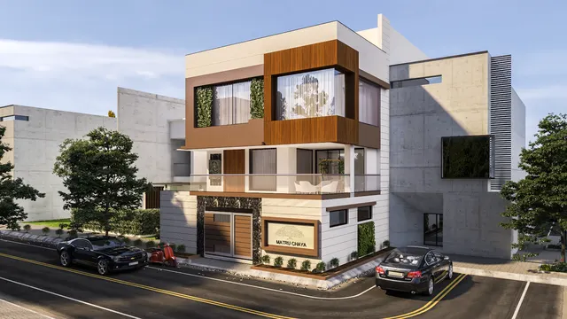



A home lift is no longer a luxury reserved for bungalows. As plots in Surat, Ahmedabad, Vadodara and across India are built three and four floors high on narrow footprints, and as families keep ageing parents at home, a small residential lift has become a sensible part of many house designs. The problem is almost never the lift itself — reliable home lifts are widely available — but the hole the lift lives in. A lift needs a shaft, a pit below the lowest floor and clear space above the top floor, and all three must be reserved in the structure before the slabs are cast. Add a lift to a finished house and the shaft usually has to be bolted on outside, cut through slabs at great cost, or dropped in a corner that was meant for something else.
The commonest mistake is to treat the lift as an interiors decision, chosen near the end like a wardrobe. By then the staircase, the beams and the slab openings are fixed, and the lift has to fit whatever gap is left. The second mistake is copying a shaft size from the internet without knowing which lift it belongs to: a hydraulic lift, a machine-room-less traction lift and a screw-driven home lift all need different shafts, pits and headrooms, and a number that suits one can be unbuildable for another. The result is a shaft that is too small for any real car, a pit that was never dug, or a top floor with no room for the lift to overrun safely.
This article explains how to reserve the right space for a small home lift: where lifts came from, the drive types used in Indian homes today, the shaft and car sizes for two, four and six persons, the pit depth and headroom each type needs, the safety and code framework under the National Building Code of India 2016, and indicative October 2026 costs. Every dimension here is a planning guide to be confirmed against the chosen lift company's general arrangement drawing (GAD) and the applicable code — a home lift is a safety-critical installation, and the vendor's drawing, not a blog, is the final authority.
Why a lift must be planned with the structure, not the interiors
A lift is a moving room that travels inside a fixed tube. The tube — the shaft or hoistway — must be continuous, plumb and structurally independent, carrying its own guide rails and absorbing the forces of a car that starts and stops. Below the lowest landing it needs a pit, a clear space that houses the buffers the car lands on and gives a technician somewhere to stand under the car. Above the highest landing it needs headroom, so the car can overrun its top stop without striking the shaft roof, and so there is refuge space above the car. None of these can be added later without major structural surgery. For this reason a lift is a decision made with the architect and the structural engineer at the planning stage — not a finish selected at the end. The single cheapest decision in the whole project is to reserve a clean shaft, pit and headroom on the drawings even if the lift is installed years later.
The three reserved spaces are easy to describe but easy to get wrong. The pit is measured from the finished floor of the lowest landing down to the pit floor. A conventional passenger lift wants a deep pit, often 1200–1500 mm, which on a ground-plus-two home means digging below the plinth. A purpose-made home lift is designed around a shallow pit, commonly about 350–500 mm and in some reduced-clearance models even less, which can sit within an ordinary plinth build-up. Headroom is measured from the finished floor of the top landing up to the underside of the shaft roof. Again a conventional lift wants a tall headroom of 3500 mm or more, while a home lift is designed to work with roughly 2300–2600 mm. These differences are exactly why the lift type must be chosen before the shaft is dimensioned — the pit and the headroom follow from the drive.
Where home lifts came from
Vertical movement inside buildings is ancient — counterweighted platforms and hand-hauled hoists were used in forts and palaces long before machinery — but the safe passenger lift is a nineteenth-century invention. The decisive step was the safety gear: a device that grips the guide rails and stops the car if the rope fails. Once a falling car could be caught, lifts could carry people, and tall buildings became liveable. Through the twentieth century the geared and gearless traction lift, hauling a car and counterweight over a sheave driven by a machine in a room above the shaft, became the standard for apartment blocks and offices. These were big machines for big buildings, and they shaped the deep pits and tall machine rooms that older codes still assume.
The home lift is a much younger idea. Hydraulic lifts, which push the car up on an oil ram instead of hauling it on ropes, suited low-rise buildings because they needed no overhead machine room and only a modest headroom — the machinery sits in a small cabinet beside the shaft. From the 1990s onwards, compact hydraulic and then machine-room-less (MRL) traction lifts were adapted specifically for houses, with small cars, shallow pits and the controller folded into the door frame or a slim cupboard. More recently, screw-driven and pneumatic home lifts have appeared that need almost no pit and no separate machine room at all. The trend across a century is clear: the machinery has shrunk and moved into the shaft, and the civil work a lift demands has steadily reduced — which is what has finally made a lift realistic for an ordinary Indian house.
Drive types used in small homes today
Four drive types turn up in Indian home-lift proposals, and the choice decides the civil work more than any other factor. A hydraulic lift pushes the car up on an oil-filled ram and lowers it by releasing oil; it is smooth, needs only a small power cabinet, tolerates a shallow pit and modest headroom, but uses more energy on the way up and can be slower. A traction lift hauls the car over a sheave against a counterweight; it is energy-efficient and smooth, and in its machine-room-less (MRL) form the gearless machine sits inside the shaft, removing the overhead room. A screw (or nut-and-screw) lift drives the car up a threaded column and is prized for needing almost no pit and no counterweight, which suits tight retrofits. A pneumatic or vacuum lift moves a round car inside a sealed tube by air pressure and needs no pit or counterweight at all, though its capacity is small. The table compares them on the dimensions that matter to the builder.
| Lift type | How it works | Typical pit | Typical headroom | Best for |
|---|---|---|---|---|
| Hydraulic | Oil ram pushes the car; power cabinet beside shaft | ≈ 350–500 mm (home models) | ≈ 2400–2600 mm | Houses wanting a smooth, simple, low-headroom lift |
| Geared / gearless traction | Car and counterweight over a sheave | ≈ 500–1200 mm | ≈ 3000–3500 mm | Taller homes where efficiency matters |
| Machine-room-less (MRL) traction | Gearless machine inside the shaft | ≈ 350–700 mm | ≈ 2500–2800 mm | New builds reserving a clean shaft, no machine room |
| Screw (nut-and-screw) | Car climbs a threaded column | ≈ 50–150 mm | ≈ 2300–2500 mm | Retrofits where digging a pit is hard |
| Pneumatic / vacuum | Air pressure moves a round car in a tube | none / minimal | ≈ 2400 mm | Small two-person lifts, self-standing, limited load |
Shaft and car sizes for two, four and six persons
A home lift is sized by how many people it carries, and the useful band for houses is two to six persons. A two or three-person lift is enough for most families and for carrying one person with a helper; a four-person lift is the comfortable middle; a six-person lift is chosen where a wheelchair plus an attendant, or furniture, must fit. The car (the inside of the moving room) is smaller than the shaft, because the shaft must also hold the guide rails, the door operator, the counterweight on one side and the running clearances. As a rough rule the shaft is about 250–400 mm wider and deeper than the car. The table gives practical starting sizes; the exact car and shaft for a given capacity vary between manufacturers, so the final shaft is drawn from the vendor's GAD.
| Capacity | Car inside (W × D) | Clear door opening | Shaft inside (W × D) | Notes |
|---|---|---|---|---|
| 2–3 person (≈ 180–225 kg) | ≈ 800 × 1000 mm | ≈ 700 mm | ≈ 1200 × 1250 mm | Compact; one person plus a helper |
| 4 person (≈ 300 kg) | ≈ 1000 × 1100 mm | ≈ 700–800 mm | ≈ 1350 × 1400 mm | The comfortable family size |
| 6 person (≈ 400–450 kg) | ≈ 1000 × 1300 mm | ≈ 800 mm | ≈ 1500 × 1600 mm | Fits a wheelchair with an attendant |
| Wheelchair-priority | ≈ 1100 × 1400 mm | ≈ 800–900 mm | ≈ 1600 × 1700 mm | Deep car so the chair turns; confirm turning circle |
Two planning points sit behind these numbers. First, the landing door width is what a wheelchair actually passes through, and 800 mm clear is the practical minimum for comfortable wheelchair use — with a car deep enough that the chair can enter and the user can face the door. A 700 mm door suits an ambulant lift but is tight for a wheelchair. Second, the shaft must be plumb and the same size top to bottom; a shaft that narrows at one floor because a beam intrudes will not pass. When the architect reserves the shaft, the beams around it are designed to frame the opening cleanly, and any lintel over the landing doors is set high enough to clear the door height, usually around 2000–2100 mm.
The pit, the headroom and the overrun
Below the lowest floor, the pit does three jobs: it houses the buffers the car and counterweight land on in an emergency, it gives refuge space so a technician can stand safely under a parked car, and it collects any water through a small sump. A conventional lift needs a deep pit, but a home lift is engineered for a shallow one — commonly about 350–500 mm, with some reduced-clearance and screw lifts needing only 50–150 mm. If a deep pit cannot be dug — for example over a basement or on rock — this is exactly when a shallow-pit home lift or a screw lift is chosen, and the decision must be made before the foundation, not after. Above the top floor, the headroom gives the car room to overrun its top stop and provides refuge space above the car roof; home lifts are designed to work with roughly 2300–2600 mm where a conventional lift would demand 3500 mm.
| Element | Conventional passenger lift | Home lift (reduced clearance) | Why it matters |
|---|---|---|---|
| Pit depth | ≈ 1200–1500 mm | ≈ 350–500 mm (screw: 50–150) | Decides whether digging below plinth is needed |
| Headroom at top floor | ≈ 3500 mm or more | ≈ 2300–2600 mm | Decides whether the top slab must be raised |
| Overrun above top stop | Generous | Reduced, model-specific | Car must clear the roof safely |
| Floor-to-floor height | As building | ≈ 3000–3300 mm suits most homes | Travel and door height depend on it |
| Pit waterproofing and sump | Required | Required | A wet pit disables the lift and corrodes gear |
Machine-room, machine-room-less and where the controller goes
Older lifts needed a machine room — a small room directly above or beside the shaft holding the hoisting machine and controller. On a house, an overhead machine room means an extra structure above the top slab, which is often unwelcome and sometimes not allowed by height rules. The machine-room-less (MRL) lift solved this by putting a compact gearless machine inside the shaft and folding the controller into a slim cabinet beside the top landing door or into the door frame. Hydraulic home lifts never needed an overhead room; their power unit sits in a cupboard beside the shaft, which can be up to a few metres away. For a small house, the practical question is simply where the control cabinet goes: reserve a slim cupboard of roughly 600 × 400 mm beside the lift on one floor, ventilated and accessible, and the lift needs no room of its own. Planning that cupboard early avoids the familiar sight of a controller box bolted awkwardly onto a finished wall.
Safety, code and emergency features
A home lift is a safety-critical installation, and the planning must respect the framework even though the detailed design belongs to the lift company. In India the relevant reference is the National Building Code of India 2016, Part 8 (Building Services), Section 5, which covers the installation of lifts and escalators, alongside the Indian Standards for lift installation and, in several states, a Lifts and Escalators Act under which lifts must be registered and periodically inspected. The architect's job at planning stage is to reserve a compliant shaft, pit and headroom, a solid structure for the guide rails, a landing door arrangement that meets the code, and the electrical supply the lift needs. The lift company's job is to supply a certified lift with the required safety devices and to commission it. Neither should be short-cut, and a licensed, reputable lift company should always be engaged.
Certain safety features are standard on a modern home lift and should be confirmed in the proposal rather than assumed. These generally include a safety gear that grips the rails if the car over-speeds or a rope or belt fails; door interlocks so the lift cannot move with a door open and a door cannot open away from a landing; an emergency alarm and two-way communication to call for help; emergency lighting inside the car; and an automatic rescue device or battery lowering that brings the car to the nearest floor and opens the doors on a power failure — important during the power cuts common in many Indian towns. Fire and life safety for the building as a whole follows NBC 2016 Part 4; in a small house a home lift is generally not an escape route, and occupants use the stair in a fire. The exact features, ratings and compliance are the vendor's responsibility and must be stated in writing.
Costs: the lift, the civil work and the maintenance
A home lift is budgeted in three parts that are easy to confuse. First is the lift itself — supply, installation and commissioning — which on this site's lift size guide is given as indicative October 2026 figures of roughly ₹8–15 lakh for a compact traction or MRL home lift and roughly ₹10–20 lakh for a hydraulic one, so most home lifts are planned at about ₹8–20 lakh. Second is the civil work: building the shaft walls, digging and waterproofing the pit, the landing openings, the structural support for the rails and the electrical supply, which is separate and varies widely with the structure. Third is the running cost: an annual maintenance contract (AMC) of roughly ₹15,000–60,000 or more per year, plus electricity, that continues for the life of the lift. The table collects the indicative figures; all are October 2026 planning numbers to be confirmed by quotation.
| Item | Indicative cost (October 2026) | Notes |
|---|---|---|
| Home lift, 2–3 person (traction/MRL) | ≈ ₹8–15 lakh | Supply, installation and commissioning |
| Home lift, hydraulic | ≈ ₹10–20 lakh | Smooth ride; power cabinet beside shaft |
| Shaft civil work | Project-specific; verify locally | Walls, openings, rail support — varies with structure |
| Pit digging and waterproofing | Project-specific; verify locally | Deeper pits cost more; shallow-pit lifts reduce this |
| Electrical supply and backup | ₹30,000–70,000 (indicative) | Dedicated circuit, earthing, ARD battery provision |
| Annual maintenance contract (AMC) | ≈ ₹15,000–60,000 per year | Runs for the life of the lift; confirm scope |
Where home lifts are going
The direction of travel is smaller civil work and cleaner installation. Screw-driven and pneumatic lifts that need almost no pit and no counterweight are spreading into Indian homes, because they can be added to an existing house with minimal structural change — sometimes standing self-supported in a stairwell void. Gearless MRL machines keep getting more compact, and battery-backed rescue has become normal rather than optional. Energy use is coming down as regenerative drives feed braking energy back and as standby consumption is cut, which matters as homes add solar. The through-line is the same one that runs across a century of lifts: the machinery shrinks and moves into the shaft, and the hole the lift needs keeps getting easier to build. What does not change is the discipline — reserve the space early, choose the drive before the structure, and let a certified lift company confirm the numbers.
| Era | Typical home vertical movement | What changed |
|---|---|---|
| Pre-1900 | Hand-hauled hoists in forts and palaces | No passenger safety gear; not for daily use |
| 1900s–1950s | Geared traction with overhead machine rooms | Safe passenger lifts, but big civil work |
| 1960s–1990s | Hydraulic low-rise lifts | No overhead room; shallower pits suited houses |
| 2000s–2010s | Machine-room-less traction home lifts | Machine in the shaft; cleaner, efficient installs |
| 2020s onward | Screw and pneumatic home lifts | Minimal pit and no counterweight; easy retrofits |
How to plan a home lift shaft, step by step
- Decide at the sketch-design stage whether a lift is wanted now or may be added later, and reserve a clean shaft either way — it is the cheapest decision in the project.
- Choose the drive type (hydraulic, MRL traction, screw or pneumatic) before dimensioning the shaft, because the pit and headroom follow from the drive.
- Fix the capacity by use: 2–3 persons for most families, 4 for comfort, 6 or a wheelchair-priority car where a chair and attendant must fit.
- Reserve the shaft plumb and the same size top to bottom, framing it with beams so no beam or lintel intrudes into the car or door path.
- Plan the pit depth and the headroom for the chosen lift, and if a deep pit cannot be dug, select a shallow-pit or screw lift at the start, not after the foundation.
- Reserve a ventilated control cupboard of about 600 × 400 mm beside the lift, and a dedicated, earthed electrical supply with provision for battery-backed rescue.
- Set the landing door at 700–800 mm clear (800 mm for a wheelchair) with the lintel high enough to clear the door head.
- Engage a licensed, reputable lift company early, take the shaft, pit, headroom and loads from its general arrangement drawing, and check everything against NBC 2016 Part 8, Section 5 and any state lift rules.
- Waterproof the pit and keep it dry, and plan safe access to the pit and to the control cabinet for maintenance.
- Confirm the safety features in writing — safety gear, door interlocks, alarm and two-way communication, emergency light and automatic rescue device.
Frequently asked questions
What is the minimum shaft size for a home lift?
For a compact two or three-person home lift, a shaft of roughly 1200 × 1250 mm is a realistic starting size; a four-person lift needs about 1350 × 1400 mm and a six-person or wheelchair-priority lift about 1500 × 1600 mm or more. The exact shaft is set by the chosen lift company's general arrangement drawing, because the car, counterweight and clearances vary between manufacturers.
How deep does a home lift pit need to be?
A modern home lift is designed for a shallow pit, commonly about 350–500 mm, and some reduced-clearance and screw-driven lifts need only 50–150 mm. A conventional passenger lift wants a much deeper pit of 1200–1500 mm. If a deep pit cannot be dug, a shallow-pit or screw lift should be chosen at the planning stage. The exact pit depth comes from the vendor's drawing.
Can a lift be added to a house that is already built?
Yes, but it is more expensive and more limited than reserving the shaft during construction. A screw or pneumatic lift that needs almost no pit and no counterweight is often the practical choice for a retrofit, standing in a stairwell void or against an external wall. A structural engineer must confirm the support, and a licensed lift company must design the installation.
Does a home lift need a machine room?
Most modern home lifts do not. A machine-room-less (MRL) traction lift keeps its gearless machine inside the shaft, and a hydraulic lift keeps its power unit in a small cabinet beside the shaft. All that needs reserving is a ventilated control cupboard of about 600 × 400 mm beside the lift, planned early so the controller is not bolted onto a finished wall later.
Is a home lift safe during a power cut?
A modern home lift should include an automatic rescue device or battery lowering that, on a power failure, brings the car to the nearest floor and opens the doors, together with an alarm, two-way communication and emergency lighting. These features are standard on reputable units but must be confirmed in writing in the proposal, as power cuts are common in many Indian towns.
Sources & standards
- National Building Code of India 2016, Bureau of Indian Standards — Part 8 (Building Services), Section 5: Installation of Lifts and Escalators
- National Building Code of India 2016 — Part 4: Fire and Life Safety
- Bureau of Indian Standards — IS 14665 (Electric traction lifts, multi-part) and related Indian Standards for lift installation and safety
- State Lifts and Escalators Acts and rules (where applicable) for registration and periodic inspection of lifts
- Neufert, Architects' Data — planning data for lifts, shafts, pits and clearances
- Lift manufacturers' general arrangement drawings (GAD) — the binding source for shaft, pit, headroom, car, door and loads
- Price ranges: indicative October 2026 estimates — confirm locally before budgeting